
Chamber concept
Component and finish register.
Inspect the external equipment, fasteners and surfaces in the chamber study. Select a component to open its location in the assembly.
Open the chamber inspector →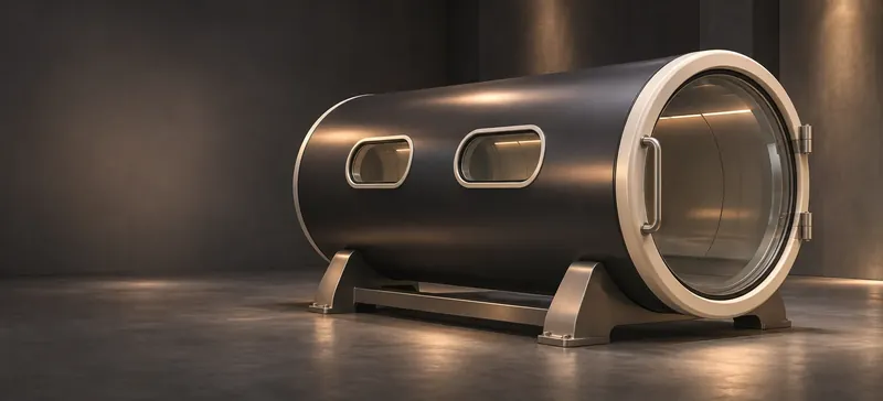
Where a finish sample could start
The base rails, lower side guard and outer trim strips are the three proposed locations for a separately evaluated appearance sample. Theis describes a chamber program. Establishing whether a finish can be used on an actual device requires the manufacturer's drawing, substrate and approved change record.
- Exterior candidate · 3 items
- A potential exterior finish sample. Define the substrate and obtain equipment-manufacturer approval.
- Mask / exclude · 3 items
- Keep this feature out of the proposed finish envelope. Confirm the actual exclusion drawing with the manufacturer.
- Supplier finish · 44 items
- Request the supplier’s existing surface specification and replacement policy.
- OEM review · 11 items
- The original equipment manufacturer must qualify this feature, its interfaces and any proposed change.
The assembly register
The concept contains 25 selectable assemblies and features, plus a bolt, washer and nut at each of 12 illustrative stations. A supplier bill of materials is required to establish the quantity, grade and finish on a physical chamber.
Envelope
- Aft shell sectionOEM review
The aft section locates the pressure envelope in this original concept. Obtain the actual vessel and change-control records.
- Forward shell sectionOEM review
The forward shell is a reference envelope. Any material or surface change at a pressure boundary belongs with the device manufacturer.
- Rear end coverOEM review
The rear closure shows the envelope extent. Its construction and connection need model-specific documentation.
- Observation viewportMask / exclude
The transparent study surface identifies a visibility and masking question. Ask for optical-surface care and replacement instructions.
- Viewport retaining ringsOEM review
Two illustrative retaining rings mark the interface between a window and adjacent bodywork. Retention and pressure qualification require manufacturer review.
- Interior service envelopeOEM review
The shaded interior marker reserves space for manufacturer-controlled oxygen-service equipment. All oxygen-path components remain under OEM review.
- Interior support formSupplier finish
An unoccupied support form gives spatial context to the cutaway. Interior surfacing, cleaning and compatibility require the device manufacturer.
Door and access
- Front access doorOEM review
The end door shows an access opening and a service-clearance question. The manufacturer owns closure qualification.
- Door observation lensMask / exclude
The lens area is excluded from the illustrative finish proposal. Obtain the actual optical material and care guidance.
- Seal / gasket exemplarOEM review
The separate ring identifies an OEM-controlled seal. Request the manufacturer’s designated replacement and inspection records.
- Door hinge assemblySupplier finish
The knuckles and pin indicate an access envelope. Confirm the supplied fitting, approved finish and sweep clearance.
- Door latch and handleOEM review
The exterior handle is a visual reference to the closure assembly. The device-specific locking and safety functions require OEM review.
Support and trim
- Support cradlesSupplier finish
Two exterior saddles illustrate the support system. Verify the actual support and load documentation before discussing any change.
- Base railsExterior candidate
The lower exterior rails provide a candidate area for an appearance sample. Confirm transport clearances and substrate ownership.
- Mounting bracketsSupplier finish
The bracket forms identify external service interfaces. Request the original supplier drawing and approved finish.
- Lower side guardExterior candidate
The detachable exterior guard provides a candidate for a separately evaluated finish sample.
- Outer trim stripsExterior candidate
The decorative trim is separated from the qualified vessel surface for discussion of color and replacement.
External electrical
- External power enclosureSupplier finish
The closed enclosure indicates a facilities coordination item. Review the manufacturer’s enclosure and service documentation.
- Illustrative power cableOEM review
The isolated exterior path illustrates a documentation request. Electrical routing, protection and acceptance belong with the device manufacturer.
- Illustrative signal cableOEM review
This exterior signal path is a separate visual trace. Obtain the supplier wiring documentation and compatibility review.
- Harness clipsSupplier finish
The clips mark a service-access question for the external harness. Verify the supplied hardware and authorized service access.
- Connector housingsMask / exclude
The connector suggests an exclusion zone. All electrical contacts and wiring remain under OEM review.
- Cable strain reliefSupplier finish
The protective sleeve marks the supplier-controlled transition into an external enclosure.
- Exterior indicator lightSupplier finish
The external lens identifies a status-display location. Color and operation in the actual device require supplier documentation.
- External sensor housingsOEM review
Exterior sensor envelopes appear for access review. Sensor function and safety qualification require manufacturer documentation.
Illustrative fasteners
- Illustrative bolt 01Supplier finish
An individually selectable fastener exemplar in the display ring. The instance count identifies the model geometry. Confirm the actual hardware schedule and manufacturer-approved finish.
- Illustrative bolt 02Supplier finish
An individually selectable fastener exemplar in the display ring. The instance count identifies the model geometry. Confirm the actual hardware schedule and manufacturer-approved finish.
- Illustrative bolt 03Supplier finish
An individually selectable fastener exemplar in the display ring. The instance count identifies the model geometry. Confirm the actual hardware schedule and manufacturer-approved finish.
- Illustrative bolt 04Supplier finish
An individually selectable fastener exemplar in the display ring. The instance count identifies the model geometry. Confirm the actual hardware schedule and manufacturer-approved finish.
- Illustrative bolt 05Supplier finish
An individually selectable fastener exemplar in the display ring. The instance count identifies the model geometry. Confirm the actual hardware schedule and manufacturer-approved finish.
- Illustrative bolt 06Supplier finish
An individually selectable fastener exemplar in the display ring. The instance count identifies the model geometry. Confirm the actual hardware schedule and manufacturer-approved finish.
- Illustrative bolt 07Supplier finish
An individually selectable fastener exemplar in the display ring. The instance count identifies the model geometry. Confirm the actual hardware schedule and manufacturer-approved finish.
- Illustrative bolt 08Supplier finish
An individually selectable fastener exemplar in the display ring. The instance count identifies the model geometry. Confirm the actual hardware schedule and manufacturer-approved finish.
- Illustrative bolt 09Supplier finish
An individually selectable fastener exemplar in the display ring. The instance count identifies the model geometry. Confirm the actual hardware schedule and manufacturer-approved finish.
- Illustrative bolt 10Supplier finish
An individually selectable fastener exemplar in the display ring. The instance count identifies the model geometry. Confirm the actual hardware schedule and manufacturer-approved finish.
- Illustrative bolt 11Supplier finish
An individually selectable fastener exemplar in the display ring. The instance count identifies the model geometry. Confirm the actual hardware schedule and manufacturer-approved finish.
- Illustrative bolt 12Supplier finish
An individually selectable fastener exemplar in the display ring. The instance count identifies the model geometry. Confirm the actual hardware schedule and manufacturer-approved finish.
- Illustrative washer 01Supplier finish
An individually selectable fastener exemplar in the display ring. The instance count identifies the model geometry. Confirm the actual hardware schedule and manufacturer-approved finish.
- Illustrative washer 02Supplier finish
An individually selectable fastener exemplar in the display ring. The instance count identifies the model geometry. Confirm the actual hardware schedule and manufacturer-approved finish.
- Illustrative washer 03Supplier finish
An individually selectable fastener exemplar in the display ring. The instance count identifies the model geometry. Confirm the actual hardware schedule and manufacturer-approved finish.
- Illustrative washer 04Supplier finish
An individually selectable fastener exemplar in the display ring. The instance count identifies the model geometry. Confirm the actual hardware schedule and manufacturer-approved finish.
- Illustrative washer 05Supplier finish
An individually selectable fastener exemplar in the display ring. The instance count identifies the model geometry. Confirm the actual hardware schedule and manufacturer-approved finish.
- Illustrative washer 06Supplier finish
An individually selectable fastener exemplar in the display ring. The instance count identifies the model geometry. Confirm the actual hardware schedule and manufacturer-approved finish.
- Illustrative washer 07Supplier finish
An individually selectable fastener exemplar in the display ring. The instance count identifies the model geometry. Confirm the actual hardware schedule and manufacturer-approved finish.
- Illustrative washer 08Supplier finish
An individually selectable fastener exemplar in the display ring. The instance count identifies the model geometry. Confirm the actual hardware schedule and manufacturer-approved finish.
- Illustrative washer 09Supplier finish
An individually selectable fastener exemplar in the display ring. The instance count identifies the model geometry. Confirm the actual hardware schedule and manufacturer-approved finish.
- Illustrative washer 10Supplier finish
An individually selectable fastener exemplar in the display ring. The instance count identifies the model geometry. Confirm the actual hardware schedule and manufacturer-approved finish.
- Illustrative washer 11Supplier finish
An individually selectable fastener exemplar in the display ring. The instance count identifies the model geometry. Confirm the actual hardware schedule and manufacturer-approved finish.
- Illustrative washer 12Supplier finish
An individually selectable fastener exemplar in the display ring. The instance count identifies the model geometry. Confirm the actual hardware schedule and manufacturer-approved finish.
- Illustrative nut 01Supplier finish
An individually selectable fastener exemplar in the display ring. The instance count identifies the model geometry. Confirm the actual hardware schedule and manufacturer-approved finish.
- Illustrative nut 02Supplier finish
An individually selectable fastener exemplar in the display ring. The instance count identifies the model geometry. Confirm the actual hardware schedule and manufacturer-approved finish.
- Illustrative nut 03Supplier finish
An individually selectable fastener exemplar in the display ring. The instance count identifies the model geometry. Confirm the actual hardware schedule and manufacturer-approved finish.
- Illustrative nut 04Supplier finish
An individually selectable fastener exemplar in the display ring. The instance count identifies the model geometry. Confirm the actual hardware schedule and manufacturer-approved finish.
- Illustrative nut 05Supplier finish
An individually selectable fastener exemplar in the display ring. The instance count identifies the model geometry. Confirm the actual hardware schedule and manufacturer-approved finish.
- Illustrative nut 06Supplier finish
An individually selectable fastener exemplar in the display ring. The instance count identifies the model geometry. Confirm the actual hardware schedule and manufacturer-approved finish.
- Illustrative nut 07Supplier finish
An individually selectable fastener exemplar in the display ring. The instance count identifies the model geometry. Confirm the actual hardware schedule and manufacturer-approved finish.
- Illustrative nut 08Supplier finish
An individually selectable fastener exemplar in the display ring. The instance count identifies the model geometry. Confirm the actual hardware schedule and manufacturer-approved finish.
- Illustrative nut 09Supplier finish
An individually selectable fastener exemplar in the display ring. The instance count identifies the model geometry. Confirm the actual hardware schedule and manufacturer-approved finish.
- Illustrative nut 10Supplier finish
An individually selectable fastener exemplar in the display ring. The instance count identifies the model geometry. Confirm the actual hardware schedule and manufacturer-approved finish.
- Illustrative nut 11Supplier finish
An individually selectable fastener exemplar in the display ring. The instance count identifies the model geometry. Confirm the actual hardware schedule and manufacturer-approved finish.
- Illustrative nut 12Supplier finish
An individually selectable fastener exemplar in the display ring. The instance count identifies the model geometry. Confirm the actual hardware schedule and manufacturer-approved finish.
Evidence for an actual device
Identify the chamber manufacturer, model, revision and document owner in the project brief. The manufacturer’s instructions govern the pressure boundary, oxygen-service surfaces, electrical assembly and service procedures.
Theis chamber program ↗FDA manufacturer-use guidance ↗Discuss an exterior finish study →