
Material samples
Moiré patterns & material combinations.
Moiré pattern viewer
Superimpose two ruled grids. Small changes in pitch or angle produce much wider bands. A printed grid on a test coupon can help an optical system measure displacement when the reference, lighting and camera are calibrated.
Ideal fringe spacing at 2° is 28.65 mm for two 1 mm gratings.
Read the pattern
The warm reference grating stays fixed. The teal sample grating moves. Both start at 1 mm pitch. At equal pitch a 2° rotation gives about 28.65 mm between adjacent bands. At zero rotation and a 5% pitch difference, the spacing is 21 mm. Shifting one layer moves the bands while their spacing stays the same. The drawing uses a fixed illustrative screen scale.
Engineers can photograph a calibrated grating before and after loading a specimen to estimate displacement. At the atomic scale, rotating two graphene sheets also creates a larger repeating pattern. Researchers measure electrical transport separately to learn how the electrons respond. Explore the twisted graphene experiment →
Zhou et al. · Fourier analysis of moiré fringes from two gratings ↗
Road-bridge experiment · displacement and rotation from sampling moiré ↗
Experimental method for measuring strain from images of a grating ↗
Watch the JoVE protocol preview on imaging strain ↗
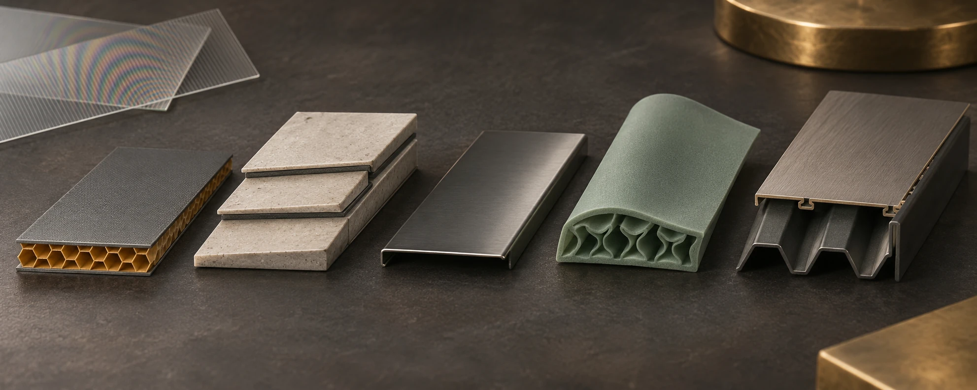
Compare material combinations
Choose two candidate architectures and inspect their layers. Hardness describes resistance to local indentation. Stiffness relates load to deformation. Strength concerns failure under a given loading mode. Fracture toughness describes resistance to crack advance.
Architected sandwich
Stiff skins around a cellular core
Bending stiffness
A continuous facing carries much of the tension or compression during bending.
Published observation
Li and Wang tested carbon-fiber-faced sandwich beams in three-point bending. Printed truss, conventional honeycomb and re-entrant honeycomb cores gave different load–deflection curves and failure modes.
Removable service panels for modular buildings
Can a service panel deflect less under the same maintenance load while staying within its mass allowance?
What to measure
Use a common span, width and loading arrangement. Record thickness and mass, the initial slope of force versus deflection, first damage, peak load and where failure starts.
What can go wrong
A stiffer panel can still dent under a small concentrated contact or lose a skin-to-core bond.
Proposed hybrid coupon
A wear face over a corrugated supporting panel
Surface hardness and peak bending load
A hard-facing candidate is evaluated for cleaning scratches and indentation.
Published observation
One team measured peak bending loads and failure of corrugated-core panels. A different team measured scratching and indentation in silica-filled coatings. The enclosure cover shown here combines those ideas in a proposed test.
Removable equipment enclosure covers
Could a cover carry its specified handling load and resist cosmetic damage without a large increase in mass?
What to measure
Compare plain, faced, ribbed and combined covers at a common width, span and loading orientation. Record thickness, mass, peak bending load and failure mode. Measure coating hardness with a specified indentation test and record abrasion loss separately.
What can go wrong
A hard face can detach as a flexible support bends. Test along and across the ribs, and inspect the interface after repeated use.
Experimental flexure of regular and hybrid corrugated-core panels ↗
Separate experimental evidence for the particle-filled finish ↗
These studies suggest civilian test coupons. The cited papers test their own specimens. A THEIS part would need its own specification, matched controls and measurements.
Prepare a comparison brief → Link to this comparison ↗All five material studies
Stiff skins around a cellular core
Li and Wang tested carbon-fiber-faced sandwich beams in three-point bending. Printed truss, conventional honeycomb and re-entrant honeycomb cores gave different load–deflection curves and failure modes.
Use a common span, width and loading arrangement. Record thickness and mass, the initial slope of force versus deflection, first damage, peak load and where failure starts.
Tiantian Li and Lifeng Wang · Bending behavior of sandwich composite structures with tunable 3D-printed core materials ↗Staggered mineral layers and compliant joints
Gupta and colleagues tested cement-paste tablets and grooved cement sheets joined by elastomer layers. As the cracks grew, their paths turned, the interlayers deformed and material bridged the openings. The measured resistance to further crack growth increased.
Compare notched, matched coupons with a continuous control. Record load, displacement and crack advance. Inspect each fracture surface.
Gupta et al. · Tough and ductile architected nacre-like cementitious composites ↗Particle-reinforced finish on a molded backing
In the tested polysiloxane finish, modified silica particles increased the load needed to produce scratch damage. The researchers also measured indentation hardness in a separate test. These results apply to their coating formulation.
Compare matched finished and unfilled controls. Measure indentation hardness, scratch depth, abrasion loss and adhesion separately after conditioning.
Silica-filled polysiloxane coatings · Journal of Colloid and Interface Science ↗A compliant facing over re-entrant cells
Bertoldi and colleagues compressed an elastomer containing a square array of circular holes. After buckling, the holes became alternating ellipses and the specimen narrowed sideways under further axial compression. The inward-angled insert drawn here is a separate design question.
Track axial and transverse strain over each load increment, before and after any buckling. Compare width change, force, recovery and repeatability with a conventional insert of the same size.
Bertoldi et al. · Negative Poisson’s ratio behavior induced by an elastic instability (Harvard full text) ↗A wear face over a corrugated supporting panel
One team measured peak bending loads and failure of corrugated-core panels. A different team measured scratching and indentation in silica-filled coatings. The enclosure cover shown here combines those ideas in a proposed test.
Compare plain, faced, ribbed and combined covers at a common width, span and loading orientation. Record thickness, mass, peak bending load and failure mode. Measure coating hardness with a specified indentation test and record abrasion loss separately.
Experimental flexure of regular and hybrid corrugated-core panels ↗